Search This Blog

Tuesday, October 26, 2010

WatRap Extruder

Since my last post, there's been huge advancements in building a reliable extruder. After reading up on articles regarding it, I decided to scrap the current design and start anew for several reasons:

1. Long Heat Zone: Dimensions of the welding tip forces at least an inch-long heat zone (likely longer because the tip is connected to an aluminum rod). This will probably cause blockage.

2. Tapping Issues: As it turns out, you need to drill an inch in order to tap 1/4".

3. Cooling Issues: Although there are some successful PTFE-less extruders out there, relying on passively-cooled aluminum fins sounds unreliable, unless they were force cooled (which we want to avoid to keep the system simple).

Here are some design decisions chosen by comparing what's out there:

1. Power Resistor as Heating Element

What's Out There: Insulated nichrome wire (Makerbot Extruder MK4), power resistor(Makerbot Extruder MK5, Nophead's extruder)

Why Power Resistor?:

- Easier to Obtain: We've looked everywhere. There are plenty of uninsulated nichrome out there, but it's pretty much impossible to find one that's insulated (at least here in Canada).

- More Reliable: When I was assembling the Makerbot extruder hot end MK4, I spent some time trying to cut the wire to the right length as multimeters tend to act finicky when measuring resistance of a thin wire. On the other hand, all you need to do with resistors is just pick one up with the right value.

- Better Maintainability: Wrapping the nichrome wire was tedious enough. The whole "unwrap the old wire, cut a new one to the right resistance, and wrap it" sounds even more tedious, especially compared to "pull the old out and put the new one in."

MK5 heats up slowly, as its thermal footprint is larger, and power resistors can't wrap around the heater barrel like nichrome wires can. However, MK5 heater block is made out of stainless steel, while we're planning to build ours with aluminum. Aluminum has a thermal conductivity that's 15 times greater than stainless steel, meaning it'll heat up fast. Yes, it also means it'll lose heat fast too, but we're hoping to nullify that issue with thorough insulation.

2. Thermocouple as Temperature Sensor

What's Out There: Thermistor(Most of DIY 3DPs out there), thermocouple (RepRap Themocouple Sensor 1.0)

Why Thermocouple?:

Less (or none at all?) Calibration Required: Sure, thermistor's easier to get, has a faster response rate, and doesn't require an interface IC, but it needs to be calibrated before it can properly measure temperature. To calibrate, you need... a thermocouple.

We don't know how a slow response time, and gradual drift of the measurement would affect reliability, but for now, calibration-free aspect of using thermocouple sounds too attractive to ignore (Provided we can obtain thermocouple wire, that is.).

3. Bowden Extruder

What's out there: Vanilla, everything-in-one-place extruder (Most of DIY 3DPs out there), Bowden Extruder (Erik's Bowden Extruder)

Why Bowden Extruder?:

- Larger Build Envelope: Our XY Stage carries the extruder, not the build stage (to maximize the build volume). Therefore, volume of the extruder is a major factor in determining the build volume. Incorporating the Bowden extruder drastically reduces the volume of the extruder (attached to the XY stage, that is).

- Less Intertia: Letting the XY stage carry less mass should bring up the speed at which we can print without stppers skipping steps.

- Relaxed Size Constraint for the Extruder Driver: Before this design revision, we were planning to use the worm gear driver for its footprint; however, as nophead pointed out in his blog post, it's not very efficient. Now that the extruder driver is out of the XY carriage, we can consider using other driving mechanisms.

However, use of Bowden Extruder introduces some feed delay between the hot end and the feed driver; consequently, NEMA 17 (Spur) geared extruder is used for more precise control.

Other design decisions include:

1. Aluminum / Stainless Steel Hot End Assembly: Since stainless steel has a lower thermal conductivity, it's used for the heater barrel. We bought a 3/8 threaded rod from Home Depot. Heater block and nozzle are still made from aluminum to ensure high thermal conductivity.

2. Custom Built Nozzle: For our new design, using a welding tip just doesn't cut it. Since we've found a good source for 0.5mm drills in Toronto, we decided to make a new nozzle. If there's one thing we're not short of, it's the machine shop access.

3. Bowden Tube Right to the Heat Zone: Since we're ordering PTFE tube for the Bowden extruder, we've decided to double its use as an insulation by putting the tube right above the heater core. This will help shortening the heat zone.

4. PTFE / Kapton Insulation of the Heater Block: Since we have a large amount of leftover PTFE sheet after making the XY stage slider, we've decided to use them to insulate the heater block. It also shields the nozzle from extruded ABS (We've had our share of problems with that).


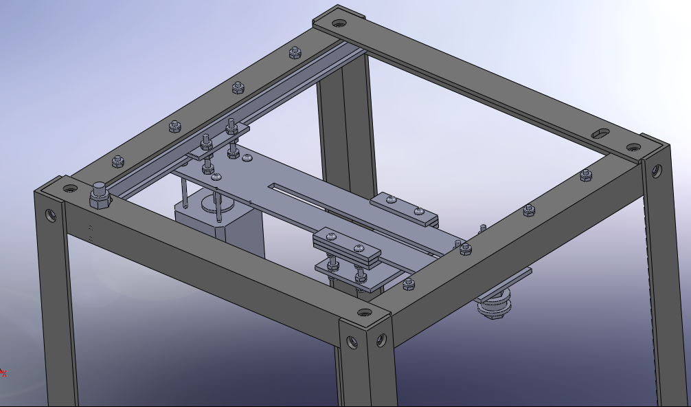
Yep, our extruder is going to look a lot different (and hopefully more reliable). I'll share the new CAD files of the extruder next time (for real this time!).


Until then,

David Shin

WatRapter Co-Lead

Monday, October 25, 2010

It's hard to keep a straight face

As funny (or punny) as the title sounds, I'm being serious. I always wondered why machines that involved keeping something straight with two tracks always had one track with play/tolerance. It makes a lot more sense to me now.

After spending a (well looking back, not so much) fruitless day of machining on Saturday to try and fix up the angle frame to get it straight so my x stage had no play, I was discouraged and quite frustrated with the process (you try successfully redrilling a countersunk hole without making the entire bolt assembly loose). I felt I wouldnt be able to get the frame properly straight, and all my wonderful visions of having a working 3d printer seemed so much farther away (have I mentioned we haven't even gotten the cartesian system done yet)? It was a little depressing for me, but then again I often find that I get discouraged too easily.

In either case we were left with an x stage that had too much play that would affect the positioning. I spent the rest of the day and most of today thinking about ways to deal with it (including cursing myself for drilling the holes on a drill press, dealing with countersinks, and the like). We considered covering up the countersunk holes with a bolt and washer assembly to remove their self-aligning nature but a quick test found that the three bolts coming together on each corner of the frame meant the bolt head had to be thinner than any bolt head known to man. What's worse was that looking at the top of the bolted frame I found there was no gaps between the horizontal and vertical members of the aluminum frame. If anything the frame members weren't poorly drilled, they weren't exactly (and I mean exactly) the right lengths.

Wait a minute. right lengths. Right angles. Aluminum angles.

Then it struck me. Why should I rely on horizontal alignment using something as finicky as two parallel tracks (or similary two rods with linear bearings on them)? Even the slightest mismatch in the tracks means they'll wobble, or worse bind. Why don't I just use one of the aluminum angles to keep myself horizontally straight? Extruded Aluminum Angle is way more accurate then my fumblings with a mill, so it should be perfect for ensuring something travels straight.

So here's the new plan: I remove the side friction wheels on one side of the x stage and place them on the other side, sandwiching an aluminum angle between two sets of bearings. This means the horizontal alignment of the x stage depends upon the straightness of the aluminum angle (which I think is fairly straight). It also means the frame doesn't have to be precisely square and can be off by a few thousands/hundredths of an inch without wobbling/binding issues. The same approach will be taken with the z stage so that the building platform travels straight up and down and doesn't wobble left and right.

Furthermore the "clamping bearings" will be mounted in slotted holes rather than simple drill holes. This arrrangment (similar to the adjustable tightness idler pulleys in the makerbot) allows me to deal with any uncertainties in the hole location by simple adjusting the position of the clamping bearings. In hindsight I should have applied this principle of "slots, not holes" more vigourously, but hey better late than never. If you're confused about what I'm talking about, don't worry. I'll make it all clear once I construct it and take a photo.

Things are looking brighter than they were yesterday, and I think there were two major design lessons that I learned.

1. stage sliding should not rely on two unparallel tracks to stay straight. Trust me even with a mill/drill press with caliper marked and center-punched holes, the tracks will be unparallel. Well that's probably more a testament to our machining skills, but hey it's hard.

2. Unless your machinery is capable of machining to within 0.00001 inches (okay thats a slight exaggeration, but only slight) or you're willing to pay a professional machinist to do a job 10x better, don't anticipate anything straight enough (you'll get bends/non-90 degree corners). Use slots/slightly larger holes so you can deal with the lack of straightness with the bolting.

Hopefully it works. We'll see next week.

-Eric

Tuesday, October 12, 2010

More changes, and construction photos!

What's changed? the z stage again.

After spending an hour or so mulling over my design of the z stage, it struck me that the rigidity/levelness of the building platform could be compared (badly) to the three possible motions of a airplane: pitch,roll and yaw. Building a solid build platform and xy stage that didn't wobble required a system that restricted any pitching, rolling or yaw movement. A quick summary of past z stage efforts

four threaded rods - pitch,roll, yaw all unrestricted (skipping of threaded rod caused all three, unstraight threaded rod cause yaw issues and general headache)
bearing design - pitch, yaw restricted (with the bearings pressing on the insides of the aluminum angle frame), roll restricted (nothing stops the platform from tilting side to side)

this revelation put me in a bit of a panic, as I didnt know what the solution could be. But then it came to me. I already use a captive system that prevents pitch yaw and roll -the x stage and its rollercoaster inspired linear guide.

You might be thinking "gee thats a heck of a lotta bearings", and you'd be right. In fact the total used in the printer is now equal to 20 (not as many as Mendel's 32, but still quite a hefty number). With each bearing costing 2 bucks, that's an additional 40 bucks worth of bearings (and they're from a surplus store, so the actual cost might be higher).

You may also think sticking with a teflon slider like the y stage would be a better option. And it might. But ball bearings are much more forgiving then teflon sliders (at least in my opinion in this early "prototyping" stage) in cantilevered systems such as the y and x axis. So until we get more people and money to test these options -which we will look for once our prototype works, reusing the ball bearing idea seems to be a safe bet.

Enough with the chit chat, lets see some model pictures and some photos of the actual metal bot.


The machine and its progress so far. Looks rather simple for now I know. The aluminum angle frame was unfortunately drilled on a drill press, which means there are a lot of parts that aren't straight and square. It's so bad that the frame doesn't even sit level on the ground (I think it has to partially do with the fact that i force bolted the pieces together, causing them to bend ever so slightly). The piece halfway down the machine with the lettering is the clear polycarbonate plastic bottom platform with the protective cover on it.


A closeup of the countersunk bolting arrangement on the angle frame. You can already see some of the gaps in the junctions of the frame pieces. I'm planning on re-drilling the holes on a milling machine next week in order to fix the bent frame issue.


A closeup of the x stage rollercoaster-inspired bearing and the attached y stage drive motor. The orange strips are kapton tape -their smoothness makes the sliding motion a lot quieter. The amount of trouble needed to secure the motor to the y stage has made me renounce locknuts for future versions, and instead embrace lockwashers and standard nutes (like that used on the angle frame).


A closeup of the underfriction wheel and side friction wheel, as well as the homemade pulley idler using a standard ball bearing with flanges made from washers. It works fairly well, and reduces the cost of having to purchase specialized idler timing pulleys.


That's everything for now.

-Eric

Monday, October 4, 2010

Change is in the air

In my last post I talked about the change in linear bearing design from rods and bushings to captured Teflon sheets. Well once again the linear bearing design took a major turn, along with some other aspects of the machine.

The first design aspect that changed was the z stage. I read a lot on reprap/makerbot forums about the challenge people had with the four threaded rod stage support. Jams, nut binding, lack of torque and crooked threaded rods seemed pretty prevalent among owners/builders, who were now switching over to a cantilever stage support design (see bothacker, Makerbot's new thing-o-matic, commercial FDM printers, etc.). This switch to a cantilevered design made more sense the more I thought about it. Having four threaded rods like RepRap's Darwin or Makerbot's Cupcake had greater costs -extra threaded rod, extra timing pulley and belt that has to be shipped from the states, extra bearings, etc.- compared to the cantilevered concept. Furthermore minimizing the threaded rod number meant the space at the top of the machine reserved for the captive bearings were now free, meaning the y stage could travel an additional 1/2 inch (from 6 to 6.5). This in turn increases our build area and gives the overall machine a bigger "bang for its buck" (ie. ratio of build area to machine footprint). You can see this by comparing the image in my last post with the image above.

For all its benefits, there was one danger I saw with using a cantilever z stage: the large overhang. The weight of the build platform would produce a moment that would have to be counteracted by the captive nut of the threaded rod (the only thing holding it up), increasing the chance of a bind and putting strain on the threaded rod. Most designs solve this by having nearby guide rods and linear bearings/bushings that take the bending force of the platform. The problem with that was the need for linear bearings, which cost in excess of 60 dollars apiece (at least in Canada) and are difficult to mount (unless you buy ones with mounting plates which tacks on another 40 dollars). They're also impossible to find at normal walk-in stores unless you're willing to go the ebay route (which isn't suitable as a long term supplier). Anyone out there that knows of a good Canadian supplier of cheap linear bearings (or linear guides), feel free to let us know in the comments section.

For the Rapter, I thought of using something else that was easier to find -ball bearings. Given that I had already purchased the ball bearings for the four-threaded rod idea, I thought reusing them to act as cam followers (ie. freewheeling guide wheels) would be a good idea. The result is the image to the left. The bearings run along the inside of the aluminum angle frame and are themselves supported by an aluminum angle structure. The positioning of the bearings (two at the back near the threaded rod, one at the front) serves to keep the build platform level and prevent any tilting. The weight of the build platform (which will be aluminum) will try and make the platform tilt forward -a counterclockwise moment in the image. To counteract that moment, the lower set of bearings on the right of the image rest against the aluminum frame and push back against the tilt. Rotation is prevented by the outboard bearings in the left of the image -any attempt to rotate will force one bearing into the frame. An additional benefit to this arrangement is the ability to space the actual heated bed from the z stage moving segment -allowing the bed to expand without binding the stage. Whether or not this works in practice, we'll have to see when its constructed.

The second design aspect changed was the x stage bearing. After a few days of modelling the teflon x stage, I began feeling a little suspicious of the possibility of binding. My suspicion was confirmed when a colleague at my co-op workplace mentioned a 2:1 rule: When applying a force that isn't at the center of the piece (which is what I'm doing for the x stage with the timing belt and pulley off to one side) the length of your sliding contact must be at least half the distance from the force point to the contact point, otherwise there's a large possibility of binding. This made sense given that any force offset from the middle of the sliding piece would produce a couple moment which will try and rotate the stage instead of pulling it. Simply put, my teflon sliding contacts had a big possibility to jam, and I wasn't interested in trying to deal with that on our first prototype model.

The solution? More ball bearings.

The image to the right shows the latest design of the x stage linear bearing. Rather than using rods and bushings/bearings (which are expensive and awkward to mount), commercial linear slides (which are easy to mount but also prohibitively expensive) or teflon sliders (which are susceptible to binding), I opted to use a bunch of bearings I found at the nearby surplus store (long term suppliers shouldn't be difficult to find) to form a linear bearing similar to rollercoaster wheel assemblies (traction wheels, side friction wheels and underfriction wheels). A rendering can be seen above, and a picture of a machined roller assembly is below:

It should be noted that just cutting that aluminum angle to size and drilling and tapping the holes fairly accurately to make two roller assemblies required about 4 hours in the machine shop -even with digital readout milling machines and a machinist on hand to assist and guide. If anything that shows just how time-consuming it is to machine something correctly. Fortunately the assemblies fit rather nicely on the aluminum angle (a small gap with the underfriction wheel, but nothing that can't be fixed by simple layering of tape or another material), and operate fairly quietly when the angle surface is covered with a layer of super-smooth kapton tape (scotch tape hasn't been tried yet, but I think it will work just as well, in addition to being cheaper and not adding an odd orange colour to the frame =P ).

The third and final change to the design has been the shifting of the x stage motor and idler pulley just beyond the confines of the aluminum angle. Looking at the machine straight on, the x stage will now jut out over the sides about 3/4 an inch on either side. Although this will affect the "clean contained cut" look of the original design, it gives us more y stage travel. We now have a little over 8 inches of x travel. close to 8 inches of y travel, and around 12 inches of z travel (assuming the extruder ends at the height of the bottom of the x stage motor). That's a theoretical build area about 4 times that of the latest makebot "thing-o-matic" and is comparable with the RepRap models, though at 1/4 the footprint of Darwin and 1/2 the footprint of Mendel. Hopefully we can keep that build area advantage.

Anyways, that covers everything on the cartesian frame side. The y stage will still use teflon sliders, as the force is applied in the middle and the lenght of contact is more than half the carriage length. We'll see how it works when we test it.


till next time,

Eric