The first design aspect that changed was the z stage. I read a lot on reprap/makerbot forums about the challenge people had with the four threaded rod stage support. Jams, nut binding, lack of torque and crooked threaded rods seemed pretty prevalent among owners/builders, who were now switching over to a cantilever stage support design (see bothacker, Makerbot's new thing-o-matic, commercial FDM printers, etc.). This switch to a cantilevered design made more sense the more I thought about it.
 Having four threaded rods like RepRap's Darwin or Makerbot's Cupcake had greater costs -extra threaded rod, extra timing pulley and belt that has to be shipped from the states, extra bearings, etc.- compared to the cantilevered concept. Furthermore minimizing the threaded rod number meant the space at the top of the machine reserved for the captive bearings were now free, meaning the y stage could travel an additional 1/2 inch (from 6 to 6.5). This in turn increases our build area and gives the overall machine a bigger "bang for its buck" (ie. ratio of build area to machine footprint). You can see this by comparing the image in my last post with the image above.
For all its benefits, there was one danger I saw with using a cantilever z stage: the large overhang. The weight of the build platform would produce a moment that would have to be counteracted by the captive nut of the threaded rod (the only thing holding it up), increasing the chance of a bind and putting strain on the threaded rod. Most designs solve this by having nearby guide rods and linear bearings/bushings that take the bending force of the platform. The problem with that was the need for linear bearings, which cost in excess of 60 dollars apiece (at least in Canada) and are difficult to mount (unless you buy ones with mounting plates which tacks on another 40 dollars). They're also impossible to find at normal walk-in stores unless you're willing to go the ebay route (which isn't suitable as a long term supplier). Anyone out there that knows of a good Canadian supplier of cheap linear bearings (or linear guides), feel free to let us know in the comments section.
 For the Rapter, I thought of using something else that was easier to find -ball bearings. Given that I had already purchased the ball bearings for the four-threaded rod idea, I thought reusing them to act as cam followers (ie. freewheeling guide wheels) would be a good idea. The result is the image to the left. The bearings run along the inside of the aluminum angle frame and are themselves supported by an aluminum angle structure. The positioning of the bearings (two at the back near the threaded rod, one at the front) serves to keep the build platform level and prevent any tilting. The weight of the build platform (which will be aluminum) will try and make the platform tilt forward -a counterclockwise moment in the image. To counteract that moment, the lower set of bearings on the right of the image rest against the aluminum frame and push back against the tilt. Rotation is prevented by the outboard bearings in the left of the image -any attempt to rotate will force one bearing into the frame. An additional benefit to this arrangement is the ability to space the actual heated bed from the z stage moving segment -allowing the bed to expand without binding the stage. Whether or not this works in practice, we'll have to see when its constructed.
The second design aspect changed was the x stage bearing. After a few days of modelling the teflon x stage, I began feeling a little suspicious of the possibility of binding. My suspicion was confirmed when a colleague at my co-op workplace mentioned a 2:1 rule: When applying a force that isn't at the center of the piece (which is what I'm doing for the x stage with the timing belt and pulley off to one side) the length of your sliding contact must be at least half the distance from the force point to the contact point, otherwise there's a large possibility of binding. This made sense given that any force offset from the middle of the sliding piece would produce a couple moment which will try and rotate the stage instead of pulling it. Simply put, my teflon sliding contacts had a big possibility to jam, and I wasn't interested in trying to deal with that on our first prototype model.
The solution? More ball bearings.
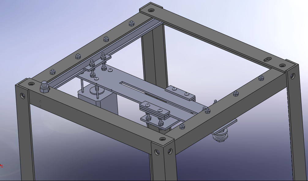
 The image to the right shows the latest design of the x stage linear bearing. Rather than using rods and bushings/bearings (which are expensive and awkward to mount), commercial linear slides (which are easy to mount but also prohibitively expensive) or teflon sliders (which are susceptible to binding), I opted to use a bunch of bearings I found at the nearby surplus store (long term suppliers shouldn't be difficult to find) to form a linear bearing similar to rollercoaster wheel assemblies (traction wheels, side friction wheels and underfriction wheels). A rendering can be seen above, and a picture of a machined roller assembly is below:
.jpg) It should be noted that just cutting that aluminum angle to size and drilling and tapping the holes fairly accurately to make two roller assemblies required about 4 hours in the machine shop -even with digital readout milling machines and a machinist on hand to assist and guide. If anything that shows just how time-consuming it is to machine something correctly. Fortunately the assemblies fit rather nicely on the aluminum angle (a small gap with the underfriction wheel, but nothing that can't be fixed by simple layering of tape or another material), and operate fairly quietly when the angle surface is covered with a layer of super-smooth kapton tape (scotch tape hasn't been tried yet, but I think it will work just as well, in addition to being cheaper and not adding an odd orange colour to the frame =P ).
It should be noted that just cutting that aluminum angle to size and drilling and tapping the holes fairly accurately to make two roller assemblies required about 4 hours in the machine shop -even with digital readout milling machines and a machinist on hand to assist and guide. If anything that shows just how time-consuming it is to machine something correctly. Fortunately the assemblies fit rather nicely on the aluminum angle (a small gap with the underfriction wheel, but nothing that can't be fixed by simple layering of tape or another material), and operate fairly quietly when the angle surface is covered with a layer of super-smooth kapton tape (scotch tape hasn't been tried yet, but I think it will work just as well, in addition to being cheaper and not adding an odd orange colour to the frame =P ).The third and final change to the design has been the shifting of the x stage motor and idler pulley just beyond the confines of the aluminum angle. Looking at the machine straight on, the x stage will now jut out over the sides about 3/4 an inch on either side. Although this will affect the "clean contained cut" look of the original design, it gives us more y stage travel. We now have a little over 8 inches of x travel. close to 8 inches of y travel, and around 12 inches of z travel (assuming the extruder ends at the height of the bottom of the x stage motor). That's a theoretical build area about 4 times that of the latest makebot "thing-o-matic" and is comparable with the RepRap models, though at 1/4 the footprint of Darwin and 1/2 the footprint of Mendel. Hopefully we can keep that build area advantage.
Anyways, that covers everything on the cartesian frame side. The y stage will still use teflon sliders, as the force is applied in the middle and the lenght of contact is more than half the carriage length. We'll see how it works when we test it.
till next time,
Eric
No comments:
Post a Comment