Search This Blog

Monday, November 29, 2010

closer to success

This past Saturday was cut short a little because of a bbq at a friend's place, so we had only a few hours of machining, rather than a whole day. Regardless we've accomplished a few things.


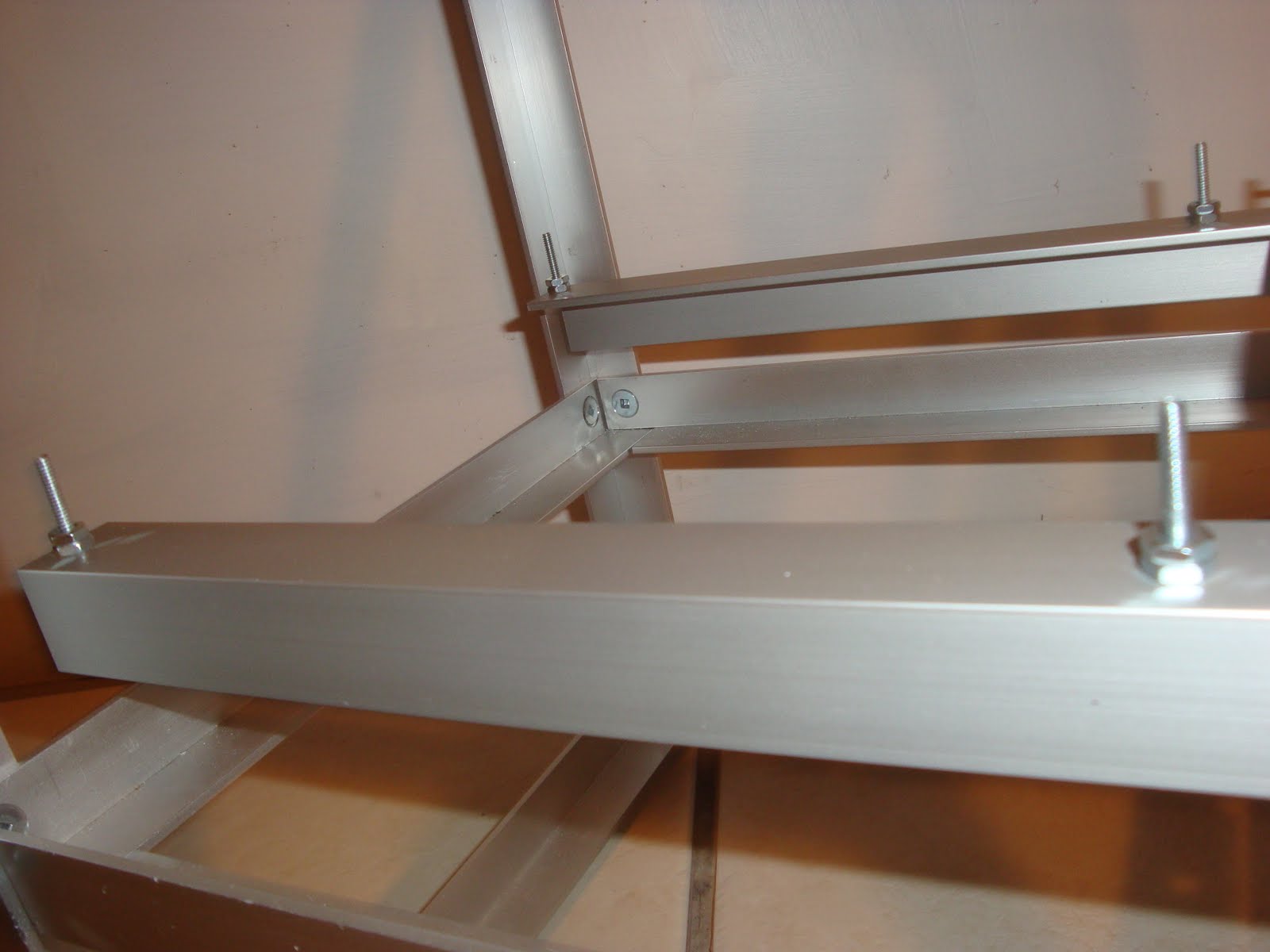
This photo shows the overall progress of the machine. You can see the main addition has been the z axis leadscrew and driving motor.


A closeup shot of the z stage motor and leadscrew junction. Here you can see the leadscrew entering the upper bearing, where the z motor shaft is coupled to it by means of a set screw (which i stupidly forgot to drill and install before putting together the assembly).

You can also see the rubber washers used to hopefully reduce the vibration effects of the stepper motor (at least we hope).


A closeup shot of the x stage motor with the rubber washers and the timing belt pulley.

Where did we get the timing belt pulley you ask?

Short answer: not in Canada.

Long answer: David's family had it custom machined in Korea (probably cheaper than the cost of customs from the U.S. XD) and brought it over when they visited him last week.


A final shot of the captive nut assembly, showing how the nut is held in place by friction and pressure. The assembly unfortunately doesn't work too well in that the nut still rotates, so it will have to be fixed in the short term by a dab of hot glue or epoxy to lock it in its place.


As it looks, the machining mechanical work seems to be nearly complete for the cartesian stage. What's left now is merely ensuring the timing belts (which have yet to be purchased) can be coupled to the moving xy stages and installing set screws for the z-axis leadscrew. Hopefully both of these things can be completed next week. After that, I'll be shifting my focus over to the electronics of the whole machine (with a lot of help from David), while he continues on the extruder design and construction.

till next time,

-Eric

Monday, November 22, 2010

Z stage

Got a few things done this past Saturday at the machine shop. It's probably just my bias since I designed and built the damn thing, but the more the printer takes shape, the sexier it looks =P


Current status of the cartesian bot. The main addition is the completed z stage and the x stage motor.


Overview of the z stage. Here you can see the cantilvered nature of the design and the position of the roller bearings I showed in my last blog post. There are four major components of the z stage (all of which can be seen in this photo): the bearings, a cross beam that holds the travelling nut, and two support beams that link the cross beam and bearings together while also supporting the heated aluminum build platform.


Here's a closeup of the junctions between the right roller bearings and the z cross beam with the right side support beam. Four bolts is probably overkill for holding it in place, but it serves to provide a very ridgid connection that won't wobble. As with everything else, double nuts are used (but not implemented yet in the photo) to ensure no bolts come loose.


A closeup of the captive nut support. You can see I have the nut locked into place by means of squeezing it up against a second (slot-adjustable as you can see) aluminum angle. The lack of side supports on the nut allows a bit of translational play to counteract the inherent wobble in the z stage stud/leadscrew. There seems to be quite a bit of friction though in some parts of the leadscrew because of the z stage wobble, so I'm going to test using a nylon nut or bronze nut in place of the current stainless steel one (if I can find one at home depot that is =P ).


Here you can see the four bolts that (will) hold the heated build platform in place. The nuts on the bolts act as spacers, allowing the heated build platform to get to its temperature of around 100-110'C (for ABS) without heating and expanding the rest of the z stage and robot. It also allows for easy levelling of the platform by adjusting the height of each nut the platform rests on.


Here you can see the beginning of the x motor being installed on the frame. To hopefully help isolate the vibrations the stepper motor makes (in addition to microstepping), I'll be adding rubber/silicone washers to the motor axle and bolts.


That's it for now. Hopefully by next week I'll be able to show the x motor securely bolted in place with the leadscrew installed.

till next time,

-Eric

Sunday, November 14, 2010

forgetting the 2:1 rule

Saturday began as a beacon of hope, the realization of failure, and then relief at redemption.


Okay that sounds melodramatic. Sorry.

Let's recap the z stage movement systmes considered so far:
-first was the four threaded rod design (Makerbot Cupcake, RepRap Darwin), which was abandoned because of high cost, complexity, loss of building space and known issues evidenced by numerous forum posts
-second was the rollercoaster element bearing , which was abandoned in favour of trying out the igus polymer bearing option (would make the machining a little cheaper and easier)

which leads to where I was when I began machining on Saturday.


Here you can see my attempt at the cantilivered z stage design. The hole in the bottom left corner of the image is one of four on the stage that are used to support the actual build platform. They act as guide/alignment posts, guiding and holding the actual aluminum build platform in place. Sticking in spacer nuts between the build platform and the shown angle frame minimizes the amount of heat transferred to the actual frame of the structure, and allows for easy levelling (this concept can also be seen with the recent makerbot blog post on "instant leveller"). The yellow object on the right of the image is the Igus slider shuttle.


Here's a top view of the stage. The big hole in the center of the frame is where the 7/16" threaded rod goes through, and where the travelling nut fits. The two smaller holes near it are for securing a another aluminum angle to prevent the captured nut from having any rotational slack.


Back view, clearly showing the two polymer shuttles.


Of course as fate would have it, I conveniently ignored the lesson I was taught about the 2:1 rule when it comes to linear plane bearings. The center of gravity of the overall assembly was way more than twice the distance from the bearings than the length of the bearings themselves (you can see that in the photos), so naturally they bound and refused to slide down the aluminum track easily.

With only a couple of hours left in the day before the shop closed, I quickly pulled out my old CAD drawing for the rolling ball bearing design and machined it. With the use of slots instead of simple drilled holes, the bearings tightly hugged the aluminum angle, providing smooth and straight motion. You can see in this photo the "master" bearing.


In this photo you can see the "slave bearing" with bearings clamping only one side of the angle to allow for minor variations in the straightness of the aluminum angle frame.

Hopefully by next week I'll be able to some photos of build platform and z nut attached to the new ball bearing sliders.


till next time,

Eric

Sunday, November 7, 2010

Straight as an arrow, smooth as a baby's bottom

Yes it's a terrible title, but it's relevant.


The machine shop was inexplicably closed two weeks ago, so we only had one day to machine anything. However there is some progress to show at least:


Here you can.... oh wait you can't really see anything changed in this picture. Oops. Oh well. You at least get to see the moose plushie my mom plopped on top of the stage (I wonder if that could be a selling point -"strong enough to support a moose").


Distinctly Canadian eh? All we need now is maple syrup and a hockey stick.


In this picture you can see the whole "binding" bearing arrangment I discussed in my last post (that may have been confusing without a picture). As the image shows, the bearings clamp both sides of a single aluminum angle, ensuring that x stage will always travel straight. The opposite side of the x stage has no side bearings so there's no chance of accidental binding or rough spots.


In this picture you can see the replacement for the y stage teflon slider that I envisioned. Turns out -as Kal our machinist friend mentioned- Teflon is a very soft, "finicky mistress". The current solution is actually an Igus drylin n-type linear slider. They're fantastically cheap (compared to ball-bearing tracks and carriages), and the company seems to have great customer service (they sent the 6 specified track lengths and carriages for free when I asked for a sample, shipped it in 3 days, and were very helpful and understanding on the phone). The slider carriages have minimal friction (being made from their proprietary iglide material, which i think is Delrin) and have replaceable glide pads (although replacing the entire carriage at 5 dollars seems like a fairly cheap option too). I'm so pleased with the result that I'll be replacing the z stage roller bearing slider with two Igus sliders, which will save me 20 dollars in bearings and reduce the amount of machining time and effort required. Hopefully I can show that in the next post. Oh and the extruder bolts onto an aluminum angle, which itself bolts through those two open holes in the image. I'm anticipating that this will allow for easy installation and modification.

Well that's it for now. Aside from the timing belts and pulleys (which we're still having trouble sourcing), the x and y stages are complete. Hopefully by next week I'll have most of the z stage completed.

till next time (or week?),

Eric
-WatRapter team co-lead